Structural Engineers at Structural Consultancy have the right knowledge and terminology to accurately do their job. Therefore, like other structural engineers, they too have certain technology up their sleeves that only they are well-acquainted with. Some of the words, which otherwise, might confuse a layman are class M soil, top plate, trench mesh, and double stud. Just as it sounds like doctors aren’t speaking in English with their medical jargon, it also feels the same with structural engineers as they throw in words like double stud, GI trap, MGB timber, and Abelflex. The list is long but one of them also includes an acronym called “cfw”.
CFW – What is it?
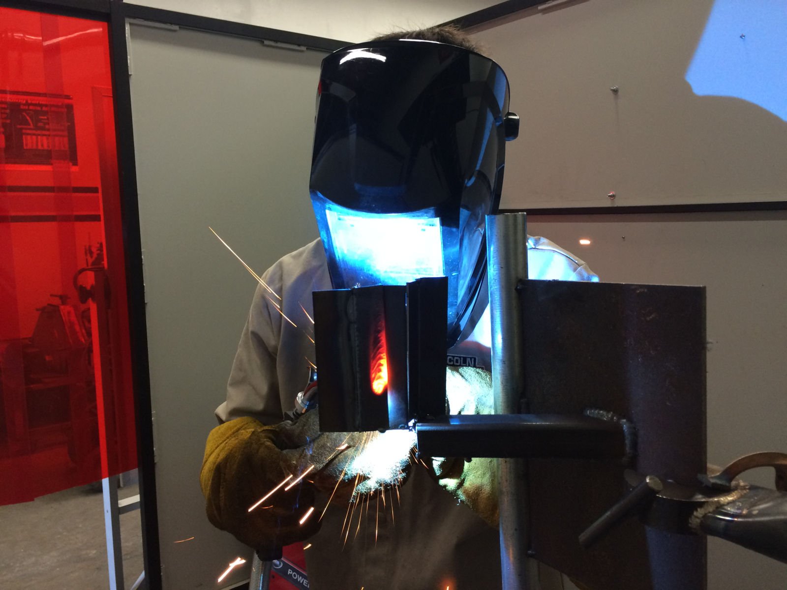
The full form of CFW at a construction site is a Continuous Fillet Weld. Typically, a fillet weld’s function is to weld together two pieces of steel, to create a connection between them in any way required for the construction or work to proceed. So, CFW is an instruction given to the boilermaker or the fabricator to make the weld continuous, which also means “not ending.”
Due to its continuous nature, the CFW weld ensures that there are no obvious entrance/start and exit/stop points made in the weld. Its other responsibility includes ensuring that a chunk of hollow steel’s insides are fully sealed.
The story of continuous fillet weld does not end here. Rather, the terminology in itself has two different specifications – each individualized as per a situation. Structural Consultancy uses its experience and technical training in the field to make the right judgment call. Their vast knowledge allows them to make a more informed decision as to which specifications will be sturdy enough to go on with their construction plans.
Specifications of the CFW:
The two types of construction fillet weld (Cfw) are 6cfw and 8cfw. The number indicated is the weld’s leg length. The engineers at Structural Consultancy will specify the length given the load that the weld is expected to endure. An additional key feature in adding the number is the strength of the parent metals.
Learn More: Structural Engineer in Melbourne

FSBW – what is it?
Welding in itself has an array of possibilities given a certain situation.
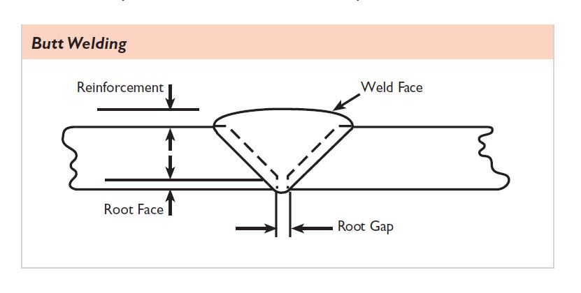
Therefore, another terminology that is largely used in the field is an FSBW weld. The full form of fsbw is Full Strength Butt Weld. When the priority is maintaining the parent weld’s full strength, and it is vital to do so for the structure to stand, structural engineers then advise using a full-strength butt weld.
Because it plays such an empirical and rare role at a construction site, creating an FSBW field is more expensive. Keeping this factor in mind and understanding that clients are on a budget when taking on a project, the team at Structural Consultancy makes sure that FSBW is only brought into place when necessary.
However, full strength butt weld is a terminology and task that comes under other welding terms such as 8 continuous fillet weld.
CFW Symbols
A construction plan is mostly made with illustrations and drawings to visualize the process of implementation. Illustrations and drawings only look neat and are also only possible if they are made with symbols. Each symbol represents a certain idea, thus, understanding what a symbol means helps to grasp and understand the depth of the big picture.
Of course, the engineers at Structural Consultancy are fully aware of the symbols. Knowing what these symbols mean will also help you make a more informed decision regarding your property with your engineers. It will also give you an opportunity to truly understand the workings being put into your property’s construction plans.
Some of the most common symbols for a fillet weld include the types of fillet welds, which are:
- Lap joint
- T-Joint
- Corner joint
Fillet welds also have an anatomy with each part having a different function. For instance, the throat of a fillet weld is used to indicate the strength of the weld, and the leg indicates the size. Hence, in layman’s terms, the “body parts” of a fillet weld normally are:
- Face
- Throat
- Leg
- Toe
- Root
There are certain elements used in a fillet weld that also have their symbols. These include:
- Staggered intermittent fillet welds
- Fillet weld on the arrow and opposite side
- Intermittent weld length and pitch
- Field weld symbol
- All around symbol
- Reference line
- Arrow line
- Tail
It is required to have face finishes in a fillet well. So, symbols for those exist too since they always have to be there. Their symbols normally come under the labels:
- Convex contour
- Concave contour
- Flat contour with processing method symbol
“Arrow,” “both,” and “other” are some of the most prominent symbols used in fillet weld symbols along with the length. these symbols allow the plan to be shared among engineers as well. For instance, if one engineer who is also the maker of a plan is not on site, and the other is, it is their expertise and knowledge that will allow them to understand the plan properly as they understand what each symbol indicates and means.

Features of a Fillet Weld
Fillet welds have a technical purpose in the field which is why Structural Consultancy is an avid user of them. However, apart from serving technical purposes, fillet welds also have features that attract customers and even engineers. Some of the most attention-grabbing features are:
- The ones up to 12-16mm leg size are more economically affordable for the clients.
- The effort that goes into edge preparation is minimal.
- They have a proper capacity for carrying loads, unlike the equivalent complete penetration butt weld. When the capacity is not specified, it is suggested to use the partial penetration one, rather than the full penetration butt weld.
- Intermittent fillet welds only prove to be economical for a certain number of uses and applications such as semi-automatic processes.
- The cost of the weld may increase significantly if more than a single pass fillet weld is used.
Read More: What Does a Structural Engineer Do?
Factors to be Considered when Making a Fillet Weld Design
Apart from the length and thickness, there are other considerations that a good structural engineer takes into account. Engineers at Structural Consultancy take full responsibility for their work, making them more cautious about considering all factors that go into making a design.
Choosing the appropriate size of the weld and the thickness of the components to carry heavy loads is the most prominent influence. Mechanical properties such as toughness, fatigue resistance, and tensile strength, along with weldability are something that structural engineers at Structural Consultancy are familiar with. For the weld to be strong, properly carry out its function, and bear heavy loads, the material is also taken under consideration by engineers. Specifying weld sizes also plays an essential role in the job being performed.
Apart from these pointers that are important and needed from a structural standpoint, engineers need to remember that as they make changes to each of these, the cost changes as well. Not only is the cost adjusted with every alteration, but so are the available safety options and serviceability of the component or structure.
Engineers at Structural Consultancy understand that cost, specifically, are key components of a client’s thought process behind hiring structural engineers. They come with a budget and prefer staying within the budget given the constraints of their pockets. Therefore, the designers at Structural Consultancy also think about:
- Choosing the most appropriate material
- Choosing a design of a welded joint that is most cost-effective.
- Using the most cost-effective process when designing the component to be welded
- Specifying the smallest weld that is acceptable for fabrication, and service, both.
- Using the welds which are as minimum in number as possible.
- Ensuring that access left for inspection and welding is nearly enough and adequate.
- Ensuring that the realistic dimensional tolerances are achievable and specified as well.
Australian Standards and Code-Check of Welds
In Australia, fillet welds also have to follow a code-check as per Australian law. Because engineers and designers at Structural Consultancy have experience across Australia, are well-familiar with the job, and are trained in the ins and outs of fillet welds, they are quite aware of the Australian Standards. Knowing what they are before they dive into their clients’ projects allows them to make a more suitable plan that is appropriate to their client’s needs, as well as meets the Australian Standards.
For fillet welds, structural engineers go according to the AS 4100, Chapter 9.6. It is assumed as per the Standard, that the strength of the weld is the same as the base metal’s strength, and it is; therefore, not checked. Particularly, in the case of a fillet weld, the element of the weld is inserted in the interpolation links that connect plates with each other. The element of the weld has an elastoplastic material diagram that solely redistributes stress along the weld length. It does so that the long weld has similar resistance.
Mathematically, the Australian Standards, according to Cl. 9.6.3.10, obligates engineers to use a given formula in designing a fillet weld subject to a design force per unit length of the weld.
The world of fillet welds is diverse. Structural Consultancy knows it at the back of its hands to assist you, but understanding its technicality may help you better discuss your situation with the engineers.
Checkout: Structural Engineer in Sydney


